
This is Part 3 of the Auburn Vanishing Edge Pool series. Series Overview | Part 1 — Design | Part 2 — Engineering

The Placer County Pre-Gunite Inspection had cleared. The steel, plumbing rough-in, and structural forms on this project had been reviewed against the engineering drawings and everything passed. Gunite day was set.
I’m usually up around 5:30 AM on gunite day. The night before, I’ve already prepared a detailed gunite plan covering all of the critical measurements, elevations, and engineering details for the shoot. By the time I’m on site at 7:00 AM, the planning is already done and the focus shifts to execution. The engineering drawings are large — 24 by 36 sheets — so I mount them to foam board before I leave the house. That way the crew can hold them, measure from them, and work with them inside the pool or in the wind without the drawings folding over. On a hillside gunite construction project in Auburn of this complexity, accuracy matters from the first shot to the last, and accessible plans are part of how you get there.
When the crew arrived, I met with the crew chief and went through the engineering details together — plans, elevations, wall thicknesses, sequencing — before anyone picked up a hose. After that, the crew got busy setting guide wires, staging hoses, and preparing equipment while I continued checking layout and elevations across the site.
The early morning on top of this Auburn hillside was something. The sun was coming up over the Sacramento Valley, the view stretching out for miles below. Then the quiet broke when the compressor truck fired up. Dust started moving across the hillside, hoses stretched across the shell, and within minutes the sound of the gunite striking the steel cage echoed through the excavation. There is always a certain energy on gunite day. Once the equipment starts running, the project begins its transformation from steel and excavation into a permanent shell.
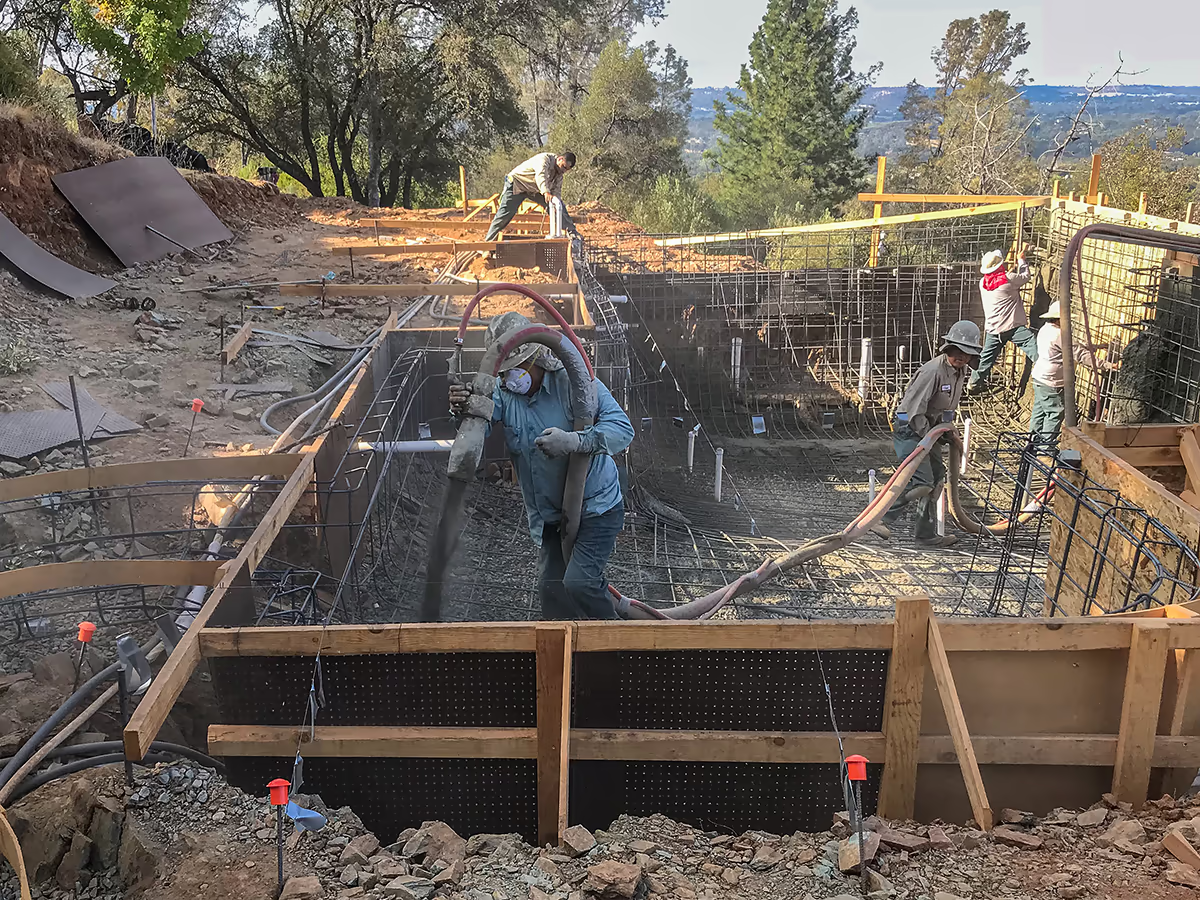
Holding Shots — How a Gunite Shoot Actually Starts
The first shots of a gunite operation are not the structural placement. They are holding shots — small amounts of gunite placed deliberately to lock portions of the steel cage into its final position before the full structural work begins. Rebar is tied, not welded. Under the force of a pneumatic nozzle, an unsecured cage can shift. Holding shots stabilize the steel so that everything that follows lands exactly where the engineering drawings require it.
Once the cage was stabilized, the crew set and leveled the guide wires — the reference lines that control bond beam elevation and vanishing edge geometry throughout the shoot. Those wires are the precision instruments of the day. Everything rods to them. On this project, they were set and verified against the laser elevation I established during the design phase — the same elevation confirmed with rebar stakes and string line the day I first stood on this hillside.
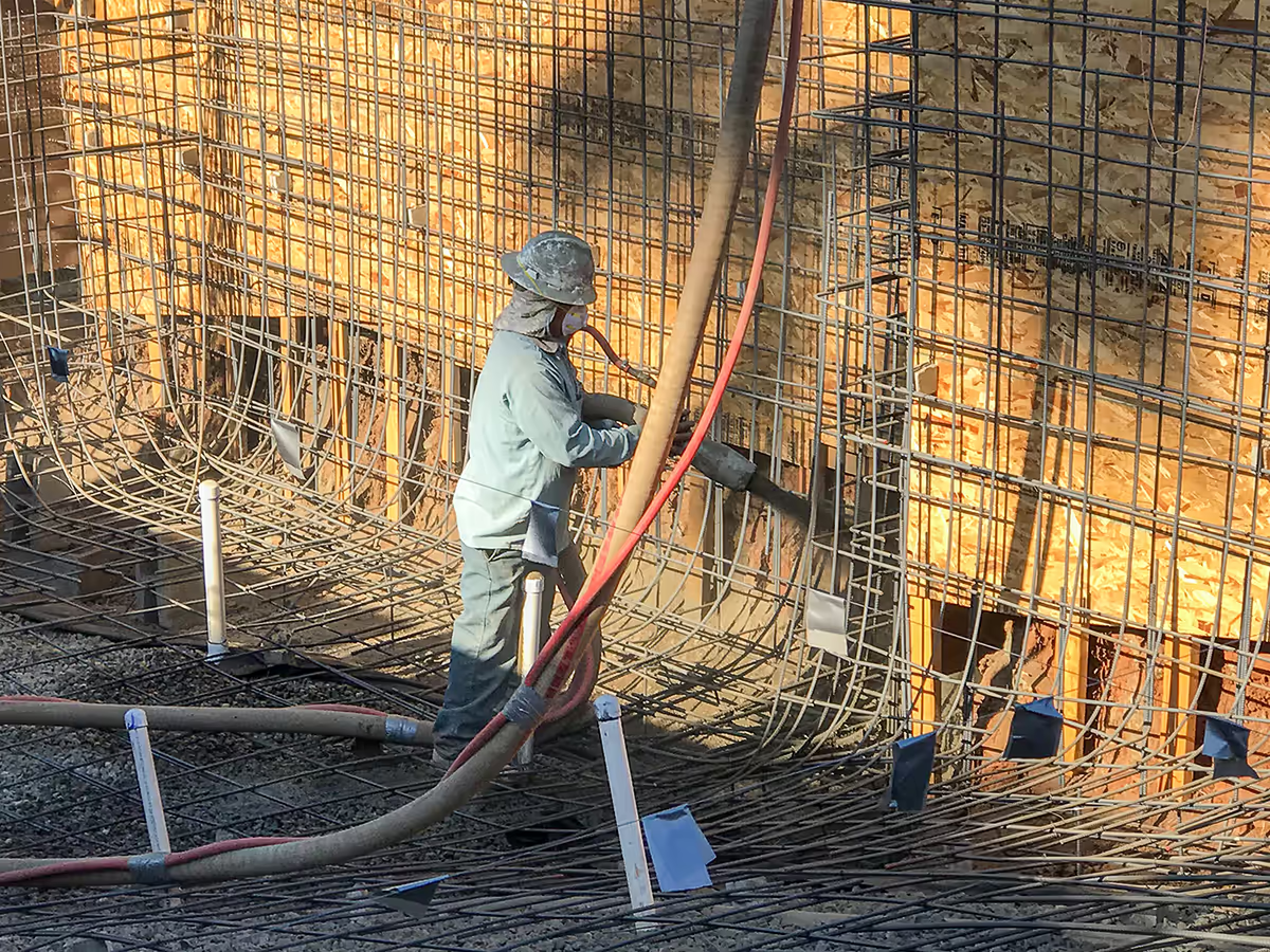
The Crew and the Operation
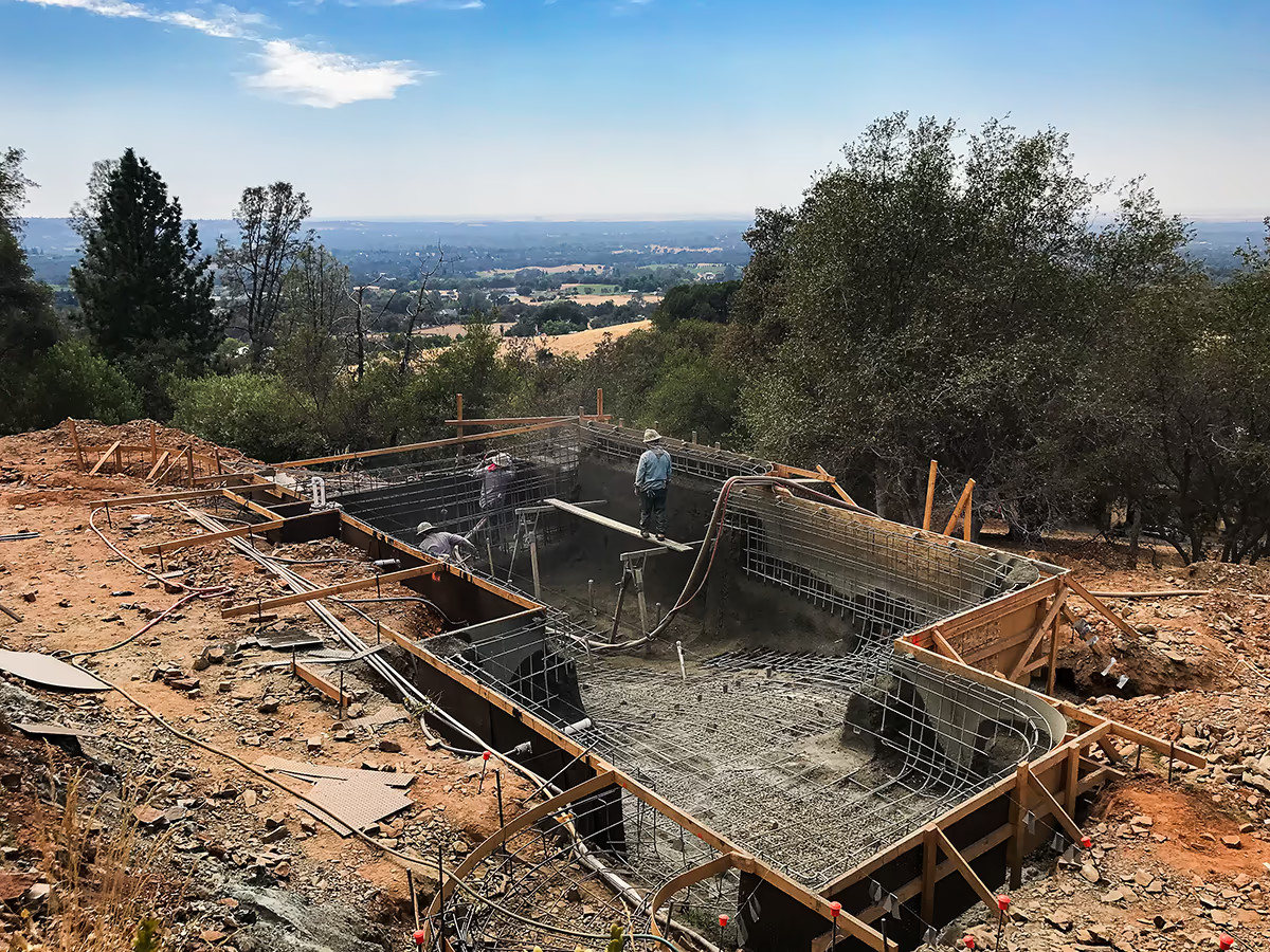
A hillside gunite operation does not run on a small crew. On a project of this scale — an elevated main pool shell, a freestanding downslope wall, a vanishing edge catch pool below the weir, and a wading pool and waterfall shell embedded into the hillside above — the crew occupies distinct zones simultaneously. No single worker can cover every surface from one position. The geometry of the site determines access, and access determines how many people you need and where they need to be.
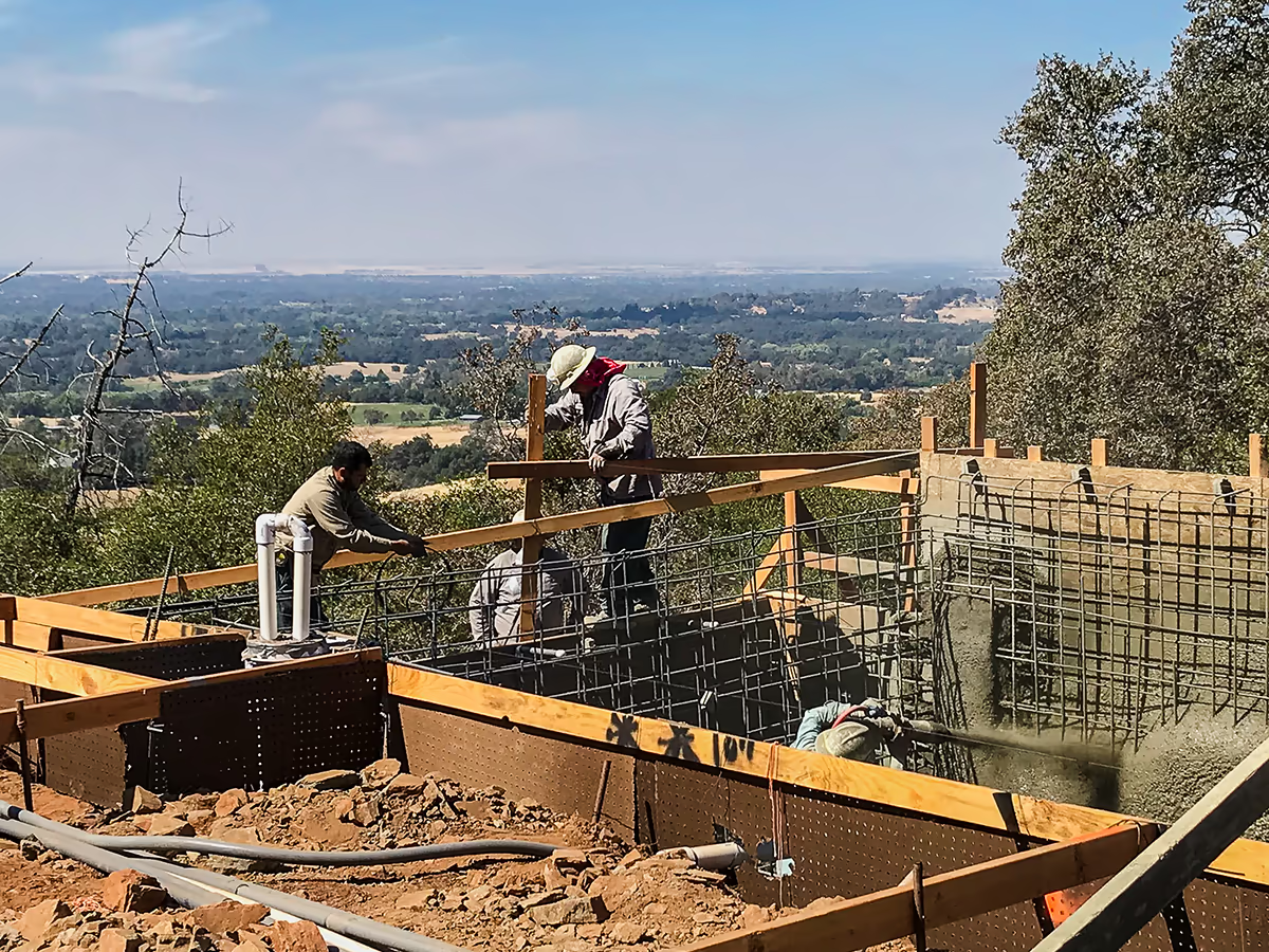
The nozzleman drives the operation. He controls the hose, the distance to the steel, and the pressure of the stream — three variables that determine whether the gunite fully encapsulates the rebar or leaves voids behind it. Behind him, the hose handler manages the line — keeping it clear, taking slack when the nozzleman moves, and preventing the weight of the hose from pulling the nozzle off target. On a hillside site with level changes and form bracing throughout, hose management is a skilled position in its own right.
While wall placement progresses, the finishing crew works the completed surfaces — rodding, floating, and maintaining the guide-wire reference plane. The bond beam team works the upper perimeter while the rebound crew continuously sweeps and removes loose aggregate from the floor ahead of the next placement pass.
Rebound is the dry aggregate that ricochets off rebar and form surfaces during gunite application — an unavoidable byproduct of pneumatic placement. It has to be removed before it cures. Rebound buried beneath fresh gunite creates a weak plane inside the shell with no structural bond to the material above or below it. On a structural hillside shell holding water under pressure, that is not acceptable.
Everybody has a job, and on a hillside gunite operation, everybody is working at the same time.
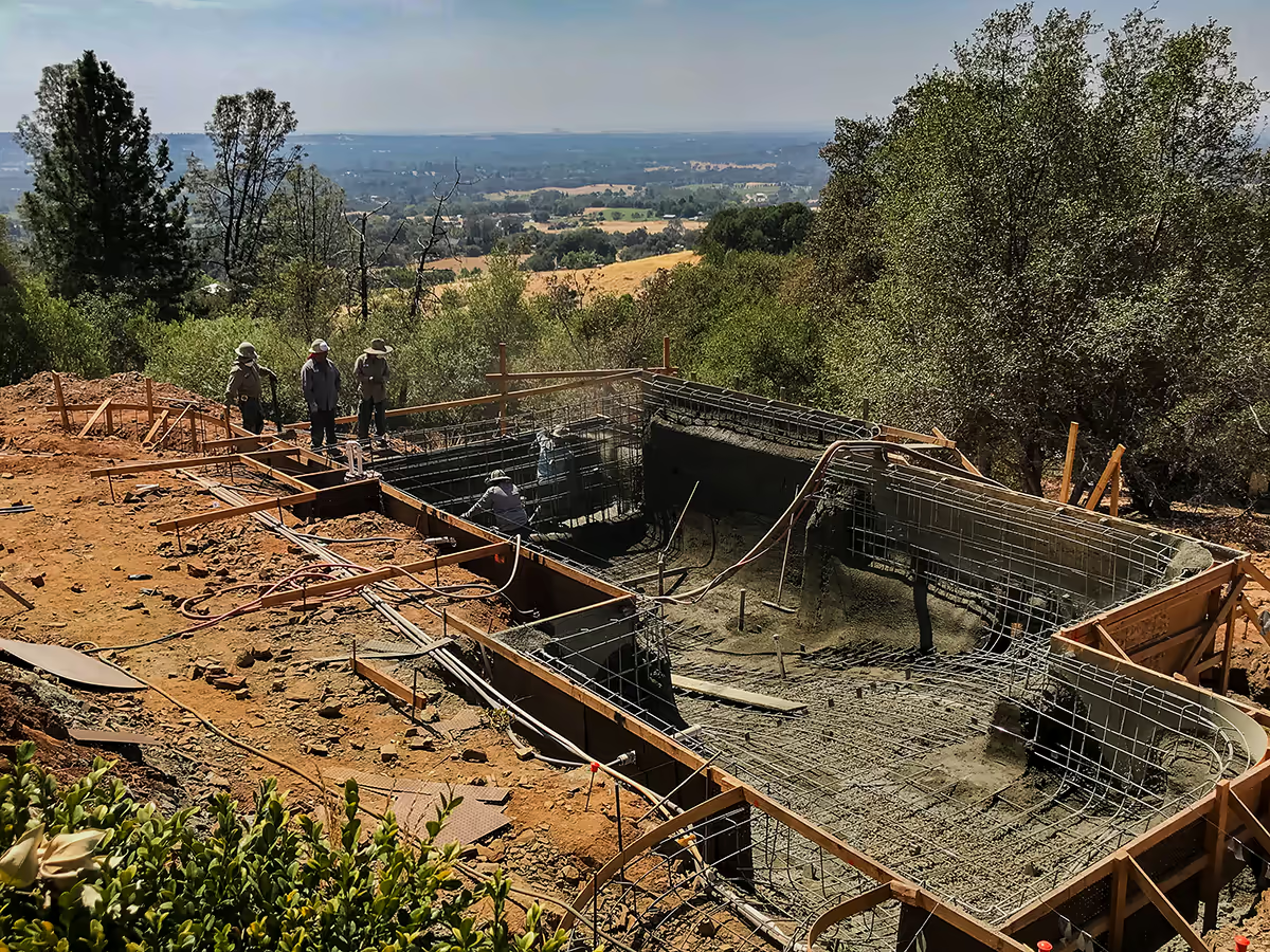

Double-Mat Steel — Why This Wall Required It
The freestanding downslope wall on this Auburn hillside gunite construction project carried double-mat rebar — two independent layers of reinforcing steel tied in parallel, rather than the single mat used in standard pool shell construction. That specification came from the structural engineering and reflects the loading conditions this wall faces.
A conventional pool wall retains water on one side against stable grade on the other. This freestanding wall retains water on one side and faces open air on the other — with the pool shell elevated more than seven feet above the hillside below. It must resist hydrostatic pressure without the passive soil resistance that backs most retaining walls. Double-mat steel is how the engineer specified that resistance.
From a gunite standpoint, double-mat is more demanding than single-mat. The nozzleman has to fully encapsulate both rebar layers — inner mat and outer mat — without creating voids between or behind either one. That requires close-range, controlled placement: the nozzle held near the form to force mix into the space behind the inner rebar, then repositioned to verify coverage on the outer face. On a wall that holds water under pressure against open air, there is no acceptable void.
Walls First — The Sequence of a Hillside Shell
The application sequence on a hillside gunite project is not arbitrary. You shoot the walls before the floor, working from the bottom of each wall upward. Wet gunite is heavy and has to be supported by the forms. Placing the floor first and then applying the walls creates a load condition on uncured gunite at the most critical joint in the shell. Walls first, floor last, is the correct sequence.
On this project, the sequence was further driven by the freestanding downslope wall geometry. That wall had to receive its full structural thickness before floor placement began — the keyway connection at the wall base had to be monolithic and complete before the floor gunite was brought up to meet it. Sequence matters here not just for quality, but for structural integrity.
With the deep and extremely thick freestanding structural walls on this project, the material volume added up quickly. The first day alone the crew shot approximately 50 yards.
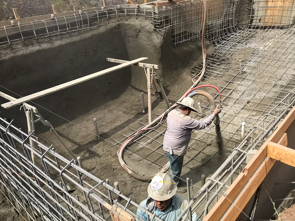
Bond Beam Elevation Control
The bond beam is the structural top course of the pool shell — the perimeter element that ties the walls together and establishes the finished coping and deck elevation. On a vanishing edge pool, the bond beam along the weir wall becomes especially critical because it establishes the elevation and geometry of the vanishing edge itself.
Getting this elevation right requires guide-wire references stretched across the full length of the weir wall at finished bond beam height. The finishers work the gunite to those guide wires using smoother rods traveling along the reference plane, bringing the entire wall to a consistent elevation from one end to the other.
The top of the weir wall on this project was not finished flat. The wall was built approximately 3 inches lower than the main pool bond beam and level across its full length, while sloping away from the pool at approximately 15 degrees toward the vanishing edge catch pool. That pitch helps direct the water cleanly over the edge and away from the pool interior.
There is some allowable tolerance at the gunite stage because the tile installation ultimately establishes the true finished spill elevation. Even so, the gunite crew still has to maintain tight control throughout the wall. If the structural shell is significantly out of level, the tile installer cannot fully correct it later.
On a vanishing edge pool, even a small variation becomes visible once the system is operating. Water always finds the low side. If the weir wall elevation is off, the spill line becomes uneven and the vanishing edge effect is compromised. Precision at this stage ultimately determines how the finished waterline performs against the Sacramento Valley horizon.
4,000 PSI — Structural Standard for Auburn Hillside Gunite Construction
Because this Auburn hillside gunite construction project was heavily structural, I made the decision to increase the gunite mix strength to approximately 4,000 PSI. Many standard swimming pool shells are commonly specified at lower strengths — often around 2,500 PSI — and that is adequate for conventional flat-lot construction.
On an elevated freestanding shell on a steep Auburn hillside, I felt it was important to build additional structural margin into the mix itself. The freestanding wall, the keyway embedment into bedrock, the catch pool — all of it carrying loads that a standard residential shell never sees. The higher-strength gunite mix was the right call. The added cement and material cost was worth the additional structural strength and peace of mind.
The Vanishing Edge Catch Pool — Finishing to Tolerance
The catch pool sits below the vanishing edge weir wall and receives all of the water that spills over it. It has to function hydraulically — volume, suction line location, and return geometry all specified in the engineering. It also has to be finished structurally — wall thickness, floor slope, and the weir wall face all subject to tight tolerance requirements.
The catch pool finisher works with a smoother rod on the weir wall face and a Fresno trowel on the catch pool floor — two tools, two surfaces, two different finishing techniques running simultaneously. The weir wall face has to be straight and consistent — the face that water will run down every time the vanishing edge operates. Guide wires stretched across the catch pool structure establish the reference plane the finisher rods to.


Catch Pool Interior — Dimensions, Guide Wires, and Finishing Sequence
The vanishing edge catch pool is a separate vessel positioned below the main pool structure. On this project, there was approximately 3 feet of vertical separation between the top of the weir wall and the top of the catch pool structure below.
Within the catch pool, the surfaces had to be finished square, plumb, straight, and true. That required precision-set guide wires stretched throughout the structure so the finishers could maintain consistent alignment and elevation during the gunite placement and finishing operation.
The catch pool floor also had to be set to a consistent elevation across its full length. The catch pool itself was designed approximately 4 feet deep and 3 feet wide. The tolerances are tight, as it is important to follow the designed plans and elevations for optimum performance.
The finishers worked the gunite using smoother rods, floats, Fresnos, and level checks throughout the operation to bring the surfaces to final grade before the shell cured permanently. Precision during this phase directly affects how the finished vanishing edge performs against the Sacramento Valley horizon.
End of Day One
On an Auburn hillside gunite construction project of this complexity, I always stay on site until the crew is comfortable with the plans, elevations, and engineering details and has no remaining questions. On this project — a two-day shoot — I expected to be present most of both days. The first day, I headed home around 3:00 PM after the crew had made substantial progress on the structural shell. By that point, approximately 50 yards of 4,000 PSI gunite were in place.
The crews always appreciate when the contractor is on site and engaged during a gunite shoot. If questions come up in the field, they get immediate answers instead of guessing or stopping production. That communication matters on a complex hillside project.
I was back on site early the next morning. The second day the crew focused on the shallow-end steps, the elevated wading pool, and the connecting channel structure between the upper water feature and the main pool.
Wading Pool and Waterfall Shell
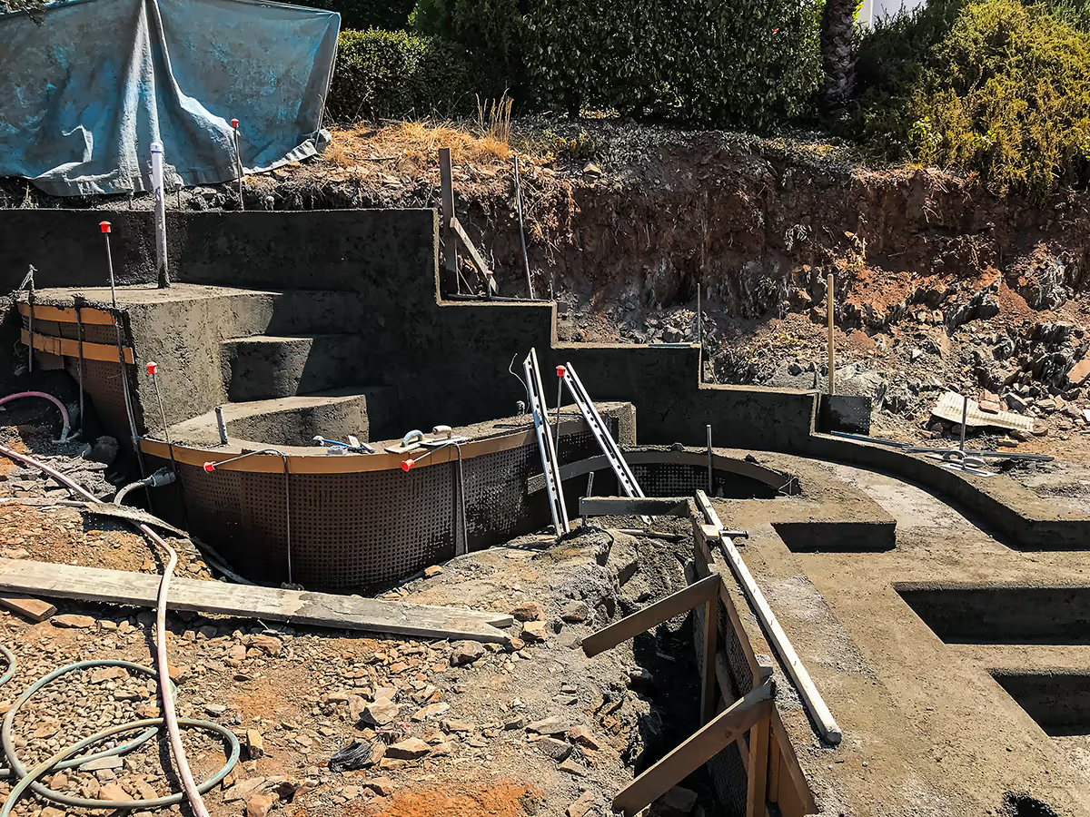
The elevated wading pool and waterfall pad structure sat higher into the hillside above the main pool, built directly against native rock with curved perforated fiberboard forms establishing the wading pool geometry. This portion of the structure was completed on the second day.
The curved form work required a different nozzle technique than the rectangular main pool walls. The nozzleman had to follow the radius continuously — nozzle angle and distance adjusting with every move around the curve to maintain full encapsulation behind the rebar grid. A straight-wall pass doesn’t translate to curved geometry. You slow down, you work closer, and you verify coverage as you go.
The transitions between the wading pool shell, the waterfall structure, and the connecting channel required the same elevation discipline as the main pool — guide wires, rod checks, and level verification throughout. The native rock cut on three sides eliminated any question about bearing material. This shell sits directly on bedrock.

Weir Wall Finishing — The View Delivered
By the second afternoon, the main pool walls and floor were complete and the crew was finishing the top of the freestanding vanishing edge weir wall — smoother rod work on the upper surface, bringing the wall to finished grade while the wall face below had already set and was beginning to cure.
Standing by the completed vanishing edge weir wall, the Sacramento Valley filled the entire horizon. The agricultural patchwork of the valley floor, the distant hills, and the blue sky were all framed by the vanishing edge structure itself. This was the exact elevation established with rebar stakes and a string line the first day I visited the property. The shell was now complete and exactly where it had been designed to be.

Deep End Bowl — Finishing the Floor
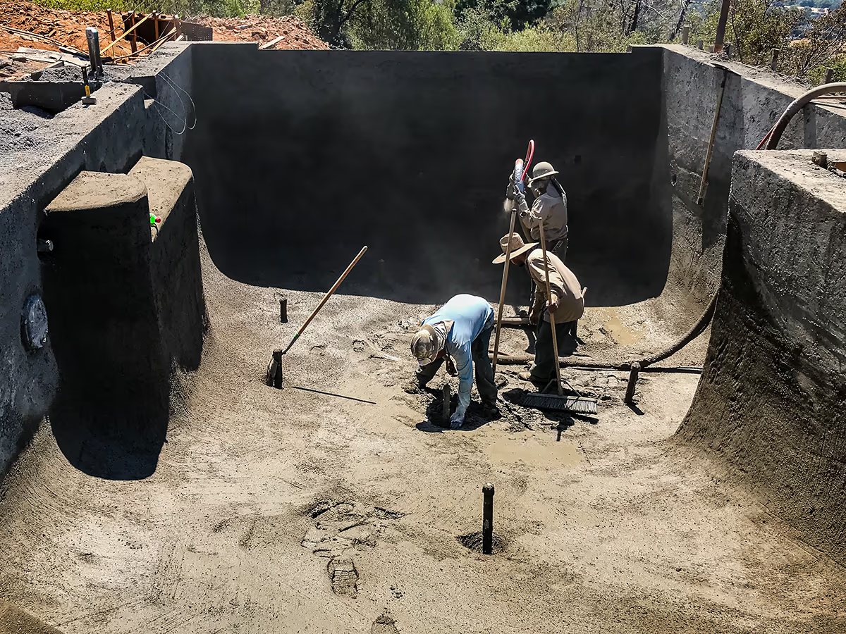
The deep end bowl is the last zone to receive floor gunite and the lowest point of the shell. The nozzleman works down in the bowl targeting the wall-to-floor coves, adding more material where stress concentrations would otherwise develop. He works the nozzle close and follows the curve. There is no shortcut on the cove work.
While the nozzleman runs the coves, a crew member cleans around the pipe penetrations. The bowl is finished with a Fresno and then given a broom finish as the crew makes their way back out of the pool, finishing their footprints as they go.
The hose handler has more to manage in the deep end than anywhere else on the shell. The line has to stay clear of freshly finished floor surfaces while the nozzleman works below him. On a hillside site, that coordination runs from the first pass on the cove to the last rod of the floor.
The Completed Shell
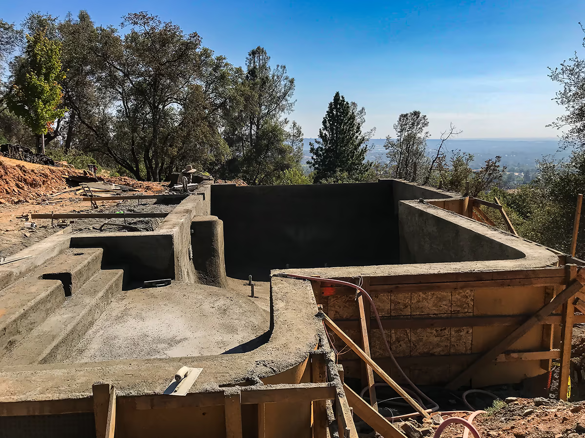
Sometime during the second afternoon, there it was — a completed pool shell emerging out of the earth. More than 82 yards of 4,000 PSI Auburn hillside gunite had transformed the excavation, steel, and forms into a permanent structure.
The main pool basin, the vanishing edge weir wall and catch pool, the wading pool, the waterfall structure — all of it gunite, all of it curing. Standing there looking across the completed shell toward the Sacramento Valley, it was rewarding to finally see the structure emerge exactly as envisioned. Even at this stage, before tile or plaster or water, you could already feel how the vanishing edge would eventually disappear into the valley below.
What Comes Next
With the shell complete and curing, the project moves into the finish trades — tile, coping, plaster, equipment installation, and the hardscape that will connect the pool deck back to the hillside grade. That work is documented in Post 4.
The gunite phase is where a hillside vanishing edge pool construction project becomes a permanent structure. Everything before it — the design, the engineering, the excavation, the steel — was preparation. The gunite days are when the preparation becomes real.
Planning a hillside pool with a vanishing edge in Auburn, Granite Bay, or the surrounding foothills?
Hillside gunite construction requires structural coordination, precise elevation control, and a crew experienced with elevated shell placement. I’ve been building these projects since 1990 — C-53 License #585004.

Jim Chandler
— Licensed Pool Builder, CSLB C-53 License #585004
Second-generation custom gunite pool builder serving the Sacramento region and Sierra foothills since 1990. Former paid Swimming Pool (C-53) Subject Matter Expert panelist for the California Contractors State License Board (2012–2017).
This post documents an active construction project personally managed by Jim Chandler — from Placer County Pre-Gunite Inspection clearance through completion of the elevated shell on a steep Auburn hillside.
Auburn Vanishing Edge Pool Series:
• Series Hub
• Part 1 — Design
• Part 2 — Engineering
• Part 3 — Construction (You are here)
• Part 4 — Tile, Waterfall, and Jump Rock
• Part 5 — Concrete Decking, Coping, and Final Finish (Coming Soon)
Planning a hillside pool in Auburn, Granite Bay, or the surrounding foothills?
Hillside vanishing edge construction requires a different level of structural planning than flat-lot pool work. I’ve been doing this since 1990 — C-53 License #585004.
Schedule a Complimentary Site Consultation
or call (916) 624-5296