
This is Part 2 of the Auburn Vanishing Edge Pool series. Part 1 — Design | Series Overview

Auburn Hillside Pool Engineering — Building Seven Feet Above Grade on a Descending Slope
The moment the string line established the vanishing edge more than seven feet above natural grade, this Auburn hillside pool engineering project changed from a design exercise into a structural problem.
What might look like a retaining wall below the pool was something far more demanding — a freestanding engineered structure responsible for supporting the elevated pool shell, resisting lateral hillside pressure, integrating the lower catch basin, and tying the entire system safely back into the hillside.
That was where the engineering phase truly began.
Developing the Structural Concept Before Engineering Begins
Before the structural engineer could start calculations, I needed to fully define the concept myself. The elevations, wall relationships, catch basin geometry, and hillside transitions all had to be established in detail before formal engineering could proceed.
A structural engineer can design a system to support a concept — but the concept has to be clearly developed first.
Using Pool Studio 3D design software along with the site’s precise elevation data, I created a detailed set of preliminary construction sections from multiple angles. These drawings communicated the structural intent of the project — wall heights, footing relationships, keyway depths, and the transition between the elevated pool shell and the descending hillside.
From the elevations alone, I could anticipate what the downslope wall would require. The site dropped at approximately three feet horizontal to one foot vertical. That geometry, combined with the seven-foot above-grade shell elevation, told me the keyway would need substantial embedment into stable native material — likely bedrock — well below the proposed pool elevation.


Preparing a preliminary engineering package like this takes days. The 3D model is only the beginning. Detailed section studies, elevation analysis, wall relationships, and structural intent all have to be organized clearly enough for the structural engineer to evaluate the concept before formal calculations begin.
Working With the Structural Engineer
That package was submitted to the project’s structural engineer for preliminary review. After evaluating the design, the engineer provided an initial proposal for structural calculations and engineering documentation. The understanding from the outset was that final recommendations could evolve based on actual site conditions and geotechnical observations made during excavation.
That is standard on hillside projects. Subsurface conditions ultimately determine how the structural system gets finalized. On a rocky Auburn hillside, you don’t fully know what you’re dealing with until excavation exposes it.
With the engineering direction established, I prepared a construction estimate with my subcontractor team and assembled a detailed proposal for the homeowner. Once approved, we moved into contract development, finalized the engineering and construction drawings, and prepared the permit package for Placer County.
Pulling the Placer County Building Permit
On a project with an exposed freestanding wall, engineered plans, and geotechnical requirements, the permit process involves more than a single counter visit. You’re working through Building, Planning, and Environmental departments, each with their own requirements and review process.
I’m thorough on my plans. Property line setbacks, septic system locations, elevation references — if a department needs to confirm a measurement, it’s on my drawings. That preparation matters when you’re standing at the planning counter with a complete set of plan sheets covering everything from keyway depths to catch basin drainage to equipment pad setbacks.
Walking out of the Placer County Building Department with a permit in hand is always satisfying. On a project this complex, it means every structural decision has been reviewed and approved. Construction could begin.
Excavation Strategy on a Rocky Hillside Grade
On a project with these structural requirements, excavation is not simply digging a hole. The forms supporting the freestanding gunite walls had to be both dimensionally accurate and mechanically stable in rocky hillside conditions during both excavation and gunite application.
I spent considerable time on site with the excavation contractor before work began — reviewing elevations, layout geometry, engineering sections, and structural relationships directly from the plans in the field. The game plan was deliberate: establish the pool position with string lines and elevation control first, excavate second, then install the forms.
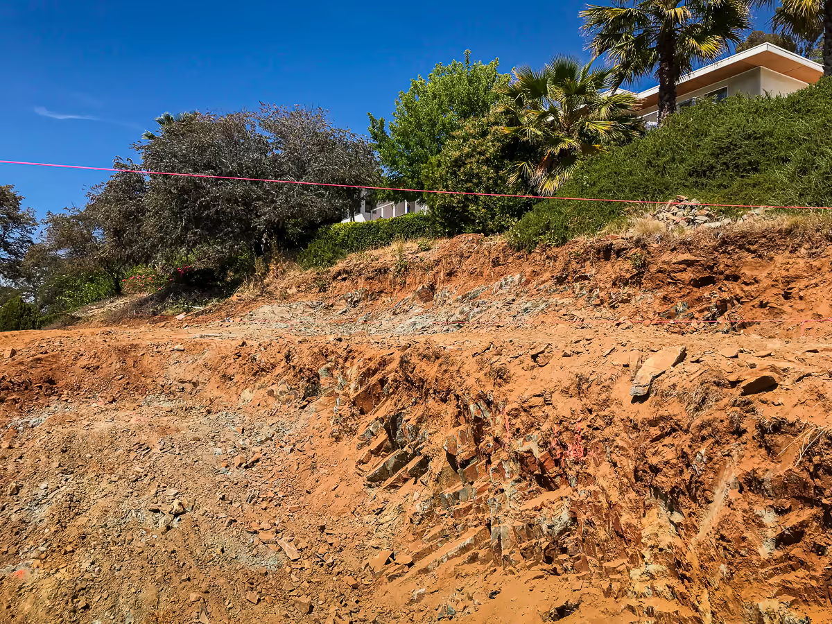
We sequenced it that way because the ground was heavily fractured rock. When you’re excavating against a rocky cut slope, trying to trim close to pre-set forms causes the sidewall to slough and collapse. Excavating first gave us a clean, stable cut before the forms went in.
The work took more than a month. The hillside had to be carefully carved into shape — developing the main pool pad, excavating the downslope structural keyway, preparing the catch basin area, establishing batter board control, and finally installing the large freestanding wall forms with extensive bracing for gunite load stability.
The excavation contractor did exceptional work under difficult conditions. Rocky ground is unforgiving. There is no room for approximation when the forms have to be plumb, dimensionally accurate, and capable of holding the structural load of pneumatically applied gunite.
First Engineering Site Visit
Once excavation and forms were complete, I requested a formal engineering site inspection before moving to plumbing and steel. This was not a Placer County requirement. On a project with a freestanding wall, a keyway embedment specification, and a catch basin below the vanishing edge, I wanted the structural engineer’s observations on the actual excavation before anything was placed.
The engineer confirmed that the soil consisted of “hard bedrock to the total depth excavated” and that the foundation conditions were suitable for support of the pool shell. The downslope keyway and catch basin excavations extended approximately 36 inches below grade, providing “sufficient embedment of the pool shell in relation to the adjacent slope face.”
Because the subgrade was solid fractured rock rather than soil, a traditional formed keyway trench was not the practical approach. The rock was over-excavated to achieve the required embedment depth. The keyway reinforcing steel schedule was applied to the over-excavated condition, and additional gunite thickness was applied to the floor. The structural engineer confirmed and approved the embedment during his site inspection before steel placement began.
One condition was noted during the inspection: pockets of loose excavated soil, approximately 2 to 5 inches deep, were observed across portions of the pool floor. The engineer recommended removal prior to steel placement.
Even though the engineer indicated he didn’t need to return if we simply cleaned it out — he said he trusted me — I didn’t want to carry a noted field condition into the next phase. I went into the excavation with the crew and personally helped shovel out every pocket of loose material down to stable bedrock. Then I asked the engineer to return and confirm the condition in writing before we moved forward.
That second visit wasn’t required. But on a project of this structural complexity, documented field verification at each phase is not overhead — it’s protection for the homeowner and the finished structure.
Building a pool on a challenging slope requires specialized structural coordination.
If you are planning a hillside project in Placer County, let’s look at your site transitions and structural options together before engineering begins.
Request a Technical Site Consultation | Direct Line: (916) 624-5296
Design Change and Second Engineering Site Visit
The second visit served two purposes: confirming the loose soil removal and addressing a design change the homeowner had requested. The owner wanted the wading pool repositioned — moved further into the hillside to better integrate with the natural grade. That change affected the wading pool’s structural relationship to the slope and required engineering input before it could be incorporated.
During that inspection, the engineer confirmed that “the loose soil was adequately removed” and that the excavation was properly prepared for the pool shell. The wading pool floor embedment was established at a minimum of 12 inches into firm native soil or bedrock, with #3 rebar at 12 inches on center each way and a minimum wall and floor thickness of 6 inches.
Several other structural details were confirmed during this visit:
The catch basin uphill wall would extend to deck elevation. The portion above the catch pool waterline was to be constructed as a raised bond beam with associated wall drainage. Critically, the catch basin and the retaining wall were to be structurally disconnected — a bond break placed between the two elements to prevent load transfer between independent structural systems.
The retaining wall plan was confirmed suitable for this project based on the observed bedrock conditions.

Gravel Fill and the Burrito Wrap — Managing Over-Excavation in Rock
Rocky excavation creates a condition that doesn’t exist on flat-lot pool construction: over-excavation. Rock doesn’t shave to a precise depth. When the cut goes deeper than the structural floor elevation — as it did on the west side of this pool — the floor has to be brought back up to the correct elevation before gunite can be placed.
The engineer specified a gravel fill system for this condition. Three-quarter inch crushed gravel, wrapped in filter fabric (geofabric), was used to build the floor back up to structural elevation. The geofabric wrap — referred to in the engineering documentation as a “burrito wrap” — contains the gravel, maintains drainage continuity, and provides a stable, non-compressible base. Near the keyway locations, the wrap also allows a clean vertical face to be formed, which is critical for proper keyway geometry.
This is not backfill in the conventional sense. Compacted soil fill under an elevated pool shell on a hillside grade would be structurally unacceptable. The gravel and fabric system maintains drainage while providing the substrate the gunite shell requires.
This is one of many details that separates hillside vanishing edge pool construction from standard residential pool work. If you’re evaluating contractors for a hillside project, the vanishing edge pool slope guide covers the structural and hydraulic requirements in depth.
Plumbing and Electrical Rough-In
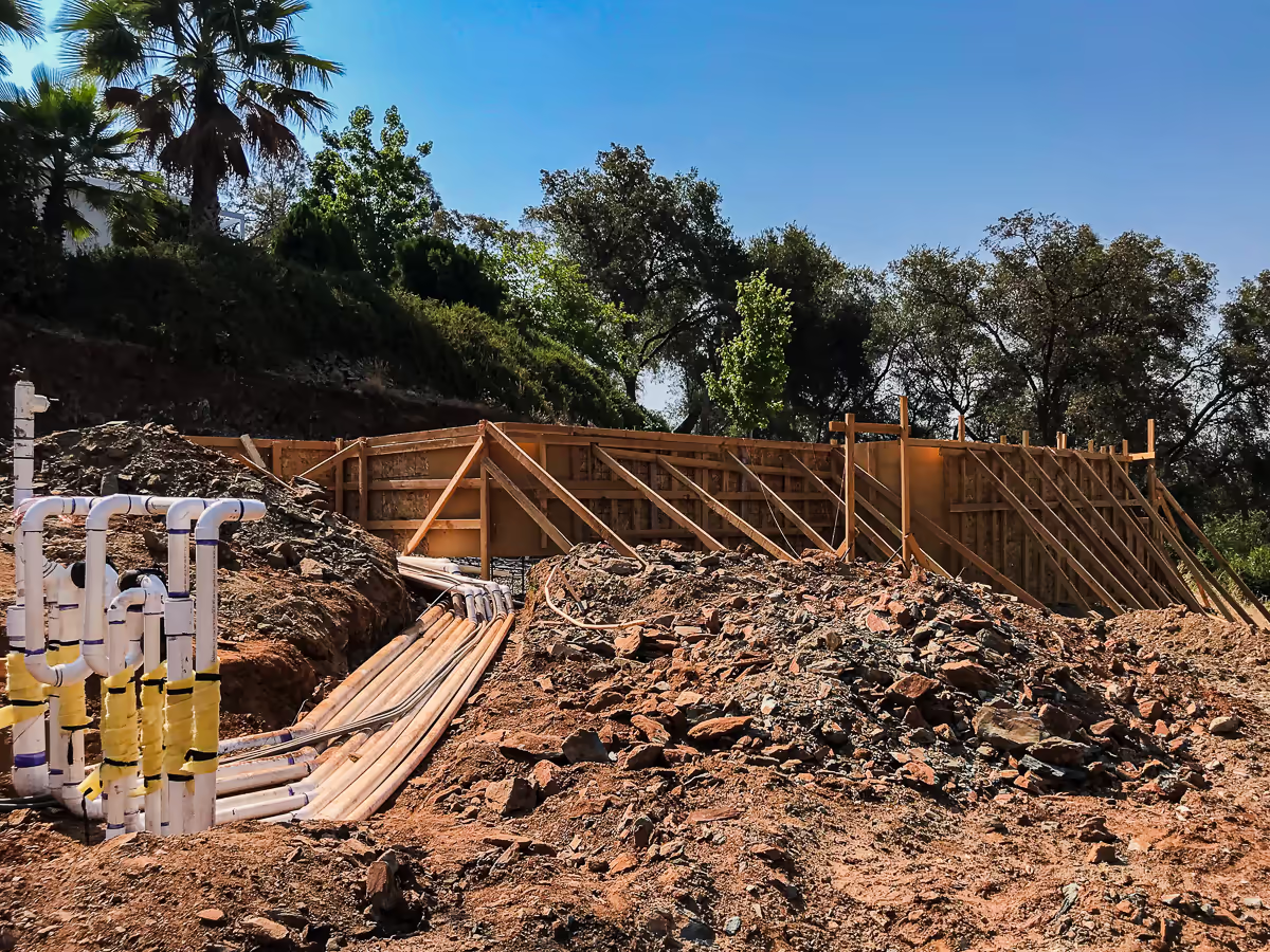
With excavation complete, keyways confirmed, and both engineering inspections documented, rough plumbing and electrical could begin. On a hillside vanishing edge project, this phase is substantially more involved than a standard flat-lot build.
The hydraulic scope reflected the complexity of the site. The main pool carried 22,498 gallons across 609 square feet. The catch basin added 1,170 gallons. The wading pool contributed another 152 gallons. Total system capacity across all three water bodies: 23,820 gallons, distributed across independent elevations and separate circulation systems.
Each water body required its own dedicated hydraulics. The main pool ran on Pump #1 — an IntelliFlo variable-speed pump handling a skimmer, a single main drain, and two floor returns serving the primary filtration circuit. A separate 1.1 HP Boost Rite on Pump #2 served the pool cleaner independently. The vanishing edge system was handled by Pump #3, an IntelliFlo XF 3 HP variable-speed unit pulling from the catch basin on a dedicated 4-inch suction line, returning water over the edge wall on a 3-inch line, and pushing four additional floor returns from the catch pool back into the main pool on lines reducing from 3 inches to 2 inches — bringing the total floor returns in the pool shell to six. Floor returns eliminate surface turbulence that wall returns create, producing the still, glass-like surface a vanishing edge pool requires to reflect the sky. The wading pool and Sierra boulder waterfall ran on Pump #4 — a third IntelliFlo variable-speed unit drawing from both the pool and wading pool through a 3-way valve with actuator, directing flow to the falls on a 2-inch return line.
All of that plumbing had to pass through and around heavily reinforced structural walls while maintaining hydraulic efficiency and future serviceability. On an elevated shell with a freestanding downslope wall, plumbing placement is part of the structural coordination — not a separate trade.
The equipment pad sat lower than the pool elevation — noted directly on the permit plans — which required specific valve configurations for suction management across the elevation differential. Overflow routing used two 1-inch lines to an approved source. Auto-fill ran on a dedicated 3/4-inch line. The hillside geometry drove several additional routing decisions in the field as excavation exposed actual bedrock conditions.
Electrical rough-in followed closely behind. Conduit runs were installed throughout the shell, catch basin, retaining walls, and deck structure before steel placement closed off access. The project drew from a 100-amp double-pole sub-panel — a dedicated load center — with a total connected load of 72 amps. All four pump circuits ran on 20-amp double-pole GFCI protection. The Boost Rite drew 5.1 amps; each IntelliFlo drew 16 amps at full load. UV and O3 systems piggybacked on the pool pump circuit.
Automation ran through a Pentair IntelliTouch i9+3 hard-wired control panel with ScreenLogic remote access, coordinating the four pump systems, lighting, sanitation, and waterfall functions together. Water treatment used a layered four-system approach: IntelliChlor salt chlorination, Paramount UV, FROG Mineral Purifier, and IntelliChem chemical management with dedicated acid and chlorine tanks.
Lighting covered all three water bodies: two 5G Color LED pool lights in the main shell, five GloBrite low-voltage colored lights distributed across the pool, catch pool, and wading pool, all fed through a dedicated low-voltage transformer. Equipotential bonding was installed throughout the shell and deck structure per NEC Article 680.26.
By the time rough-in was complete, the hydraulic and electrical infrastructure supporting the entire project was embedded in place — waiting for the steel that would lock it in permanently.
Steel Placement
With plumbing and electrical rough-in complete, the project moved into one of the most critical phases of the entire build — steel placement.
On a standard swimming pool, the reinforcing steel primarily forms the structural shell itself. On this Auburn hillside project, the steel cage also had to function as part of a freestanding retaining system supporting a vanishing edge pool elevated more than seven feet above natural grade.
The structural schedule required multiple reinforcing conditions working together throughout the shell, retaining wall, freestanding wall, keyway, catch basin, and wading pool. Much of the steel placement was driven directly by the hillside geometry and the exposed bedrock conditions verified during excavation.
The downslope freestanding wall carried both exterior and interior horizontal reinforcement, with vertical steel on the exposed face — all tied into a deepened structural keyway excavated into firm native material. The keyway reinforcement ran continuously each way and lapped a minimum of 36 inches into the wall steel above, creating a monolithic structural connection between the elevated shell and the embedded footing below. That lap length is not a detail — it is what makes the wall and keyway behave as a single structural element under lateral hillside load.
Unlike a conventional retaining wall poured separately from the pool, this structure was an integrated gunite system. The wall steel, floor steel, radius reinforcement, raised bond beam reinforcement, and vanishing edge reinforcement all had to align precisely before a single yard of gunite could be applied.
Maintaining proper steel clearance throughout the shell required constant attention. The engineering drawings specified minimum soil clearances, reinforcement lap requirements, footing reinforcement dimensions, and wall thickness transitions at the exposed hillside sections. Steel spacing varied by wall height, retained slope condition, and the structural relationship between the freestanding wall and the descending grade behind it.
The vanishing edge wall introduced another layer of complexity. Its steel had to transition continuously into the catch basin structure below while remaining structurally independent from adjacent retaining wall elements where bond breaks were required. That separation is critical on elevated vanishing edge construction — independent structural components expand, settle, and respond to hillside moisture differently over time, and the steel has to reflect that from the beginning.
The catch basin reinforcement extended higher than a typical overflow perimeter system because portions of the basin wall continued upward into a raised bond beam at deck elevation. Additional drainage provisions and reinforcing transitions were incorporated behind those walls to manage hillside moisture conditions above the catch basin.
The wading pool and waterfall structures required their own reinforcing schedule. The shell was embedded directly into native material, with continuous steel through the floor and walls supporting both the shallow water vessel and the Sierra boulder waterfall feature above.
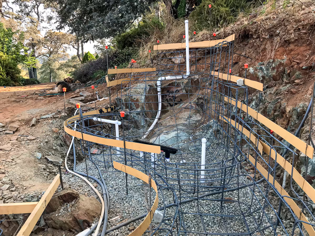
Several large natural boulders integrated into the design required dedicated structural support pads beneath the gunite shell — locations that received additional reinforcing steel and localized structural thickening to distribute concentrated rock loads safely into the shell structure.
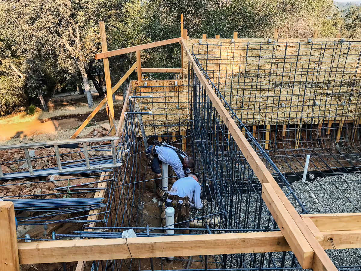
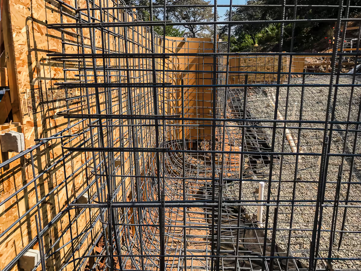
By the end of the steel phase, the entire project had transformed from excavation and forms into a fully interconnected structural framework. Every radius, wall transition, keyway, footing, raised bond beam, and vanishing edge detail now existed in steel — tied together and suspended above the Auburn hillside, waiting for gunite.
The amount of reinforcing steel involved on a project like this is dramatically different from a conventional backyard pool. At this stage, you could already see the structural intent of the design long before the first yard of gunite was applied.
Auburn Hillside Pool — Ready for Gunite
By the time steel placement was complete on this Auburn hillside project, the structural system existed in three dimensions for the first time. The freestanding downslope wall, the keyway embedment into native bedrock, the catch basin geometry, the wading pool position — all of it was now formed and steel-reinforced, ready for gunite.
Every decision made during the engineering and excavation phases — the keyway depth verified in the field, the bond break between the catch basin and retaining wall, the gravel burrito system managing the over-excavated west floor, the structural disconnection of independent wall elements — was now built into the steel layout.
What comes next is the gunite phase: the point where structural design becomes concrete and the elevated shell begins to take its final form above the Auburn hillside.


Jim Chandler
— Licensed Pool Builder, CSLB C-53 License #585004
Second-generation custom gunite pool builder serving the Sacramento region and Sierra foothills since 1990. Former paid Swimming Pool (C-53) Subject Matter Expert panelist for the California Contractors State License Board (2012–2017).
This post documents an active construction project personally managed by Jim Chandler — from structural engineering coordination through Placer County permit and pre-gunite inspection.
Auburn Vanishing Edge Pool Series:
• Series Hub
• Part 1 — Design
• Part 2 — Engineering (You are here)
• Part 3 — Construction
• Part 4 — Tile, Waterfall, and Jump Rock
• Part 5 — Concrete Decking, Coping, and Final Finish (Coming Soon)
Planning a hillside pool in Auburn, Granite Bay, or the surrounding foothills?
Hillside vanishing edge construction requires a different level of structural planning than flat-lot pool work. I’ve been doing this since 1990 — C-53 License #585004.
Schedule a Complimentary Site Consultation
or call (916) 624-5296