
This is Part 3 of a four-part series documenting the Rocklin Small Yard Pool project — a small yard pool in Rocklin, California built on a constrained backyard site with a steep slope, nine feet of grade change, and a 3-foot-9.5-inch access corridor. Part 1 covers the design and site planning. Part 2 covers the excavation. This post covers the structural steel, plumbing, and two-day gunite shoot.
Rocklin pool retaining wall construction required structural steel, plumbing rough-in, and a two-day gunite shoot — all executed as one integrated system. With the excavation complete and the structural engineer’s soil approval in hand, the rebar, plumbing, and gunite phase began. On a constrained backyard slope like this one, the retaining wall and the pool shell are not separate steps — they are the same operation, designed and inspected as one system.
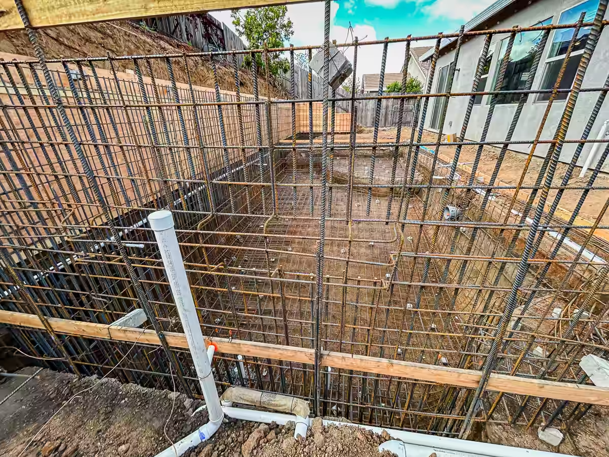
Rocklin Pool Retaining Wall Construction: Plumbing First, Then Rebar
The correct construction sequence on an engineered pool is plumbing first, rebar second. The pool plumbing system was installed before the rebar cage was tied. Every line — main drain, returns, suction — along with the pool light conduit and electrical conduit, was positioned first so that the rebar could be installed around these elements with two clearance requirements maintained throughout: a minimum of three inches between the reinforcement and the soil, and a minimum of one inch between the plumbing and the reinforcement — both specified in the structural engineering plans. Installing these elements after rebar makes achieving that clearance requirement difficult and risks compromising the structural cover specification.
This project was built to one standard engineering pool plan and four special detail sheets. The engineering plan set consisted of:
- SP1.0 — Structural Engineering Standard Pool Plan: engineering specifications for the pool structure
- CRW2 — Gunite Retaining Wall: retaining wall specifications and engineering details
- CS107 — Extended Raised Bond Beam (2:1 Backslope): engineering details for bond beam construction with 2:1 backslope
- CS123 — Exposed Extended Raised Bond Beam: engineering for extended bond beam with exposed finish
- RW1 — Gunite/Masonry Wall: structural details for gunite and masonry walls
The four special detail sheets exist because this project required conditions that a standard pool plan does not cover — a five-foot structural retaining wall, a hillside backslope, an exposed bond beam finish, and the interface between the gunite wall and the stacked block wall system two feet six inches above it. Each detail sheet was engineered specifically for the conditions present on this site.
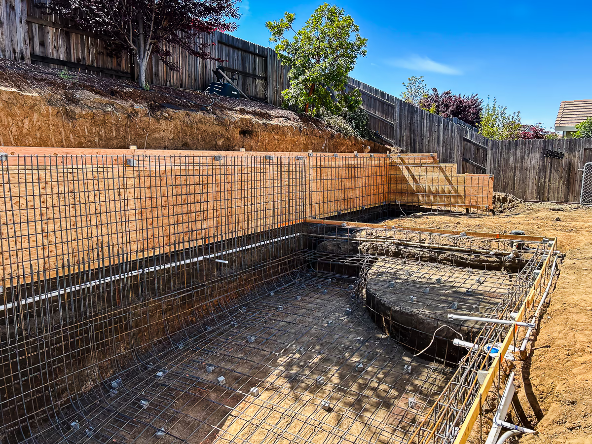
The rebar was installed per those special detail plans. The retaining wall steel and the pool shell rebar are not separate systems — they were designed, inspected, and gunited as one integrated structural assembly. The wall steel ties directly into the pool shell cage. There is no joint between them.
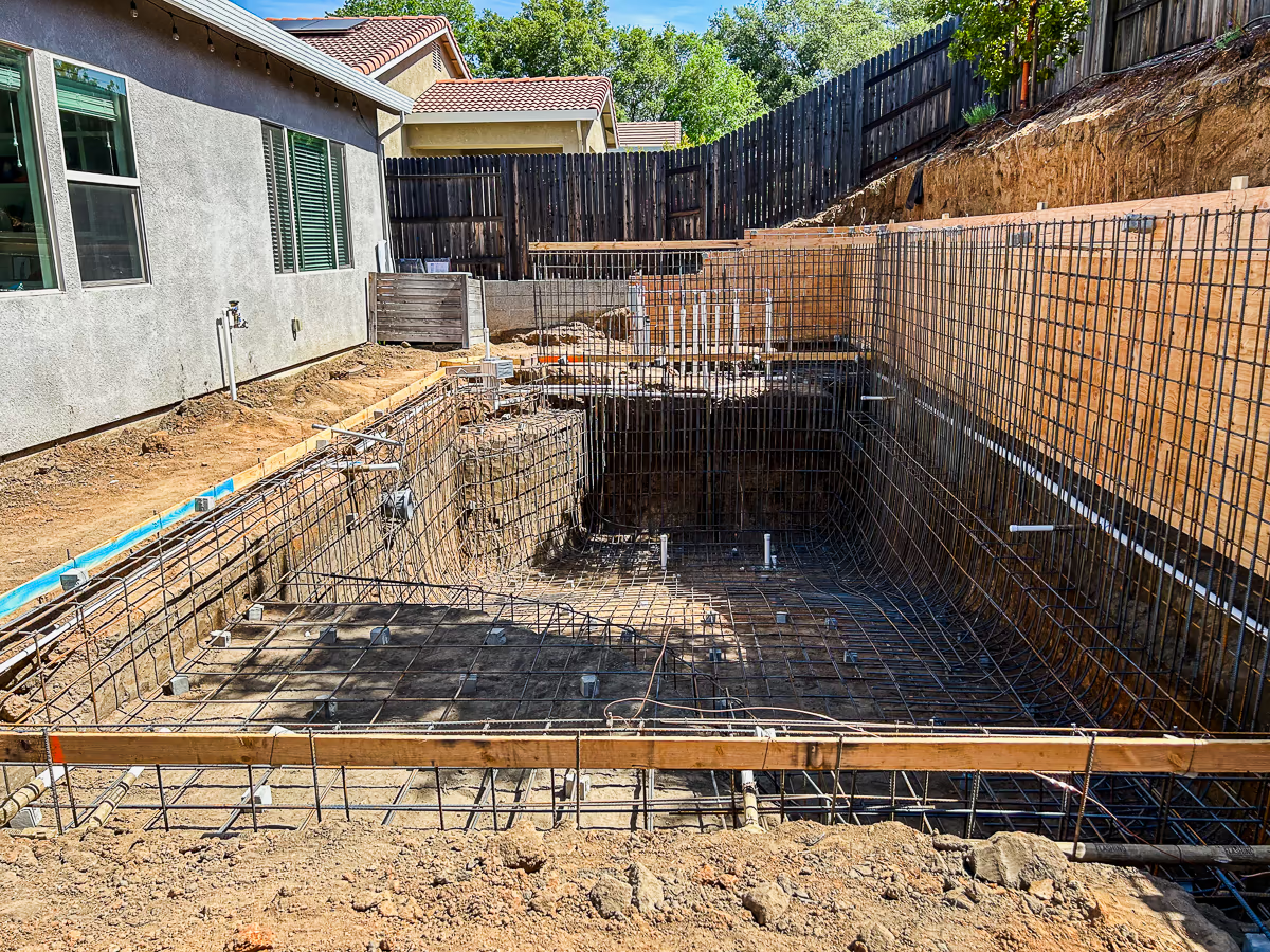
Dobie concrete bricks are placed throughout the rebar cage to maintain the concrete cover specified in the structural drawings. Cover is not optional — it is what maintains the required distance between the soil and the steel so the gunite can fully encapsulate the reinforcement and protect it from corrosion. On an engineered retaining wall system carrying nine feet of grade, proper cover is a structural requirement, not a finish detail.
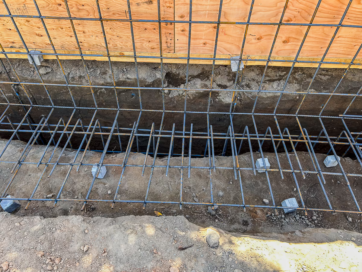
Once the shell is applied, the plumbing lines are permanently encased. There is no accessing them without cutting through the structure. Getting the sequencing and clearances right before gunite is the only opportunity to do so.
Plumbing Pressure Test Before Gunite
When the pool plumbing is complete, the system is pressurized and the gauge is monitored. The system held at 35 PSI or higher. Every line must hold that pressure before the shell is shot and the pool filter system is installed. The gauge stays on the system through the entire gunite and construction operation — any pressure drop during application indicates a leak that must be located and repaired before the shell sets.
The City of Rocklin’s pre-gunite inspection requirements specify water lines on test at 35 PSI — the same standard this project was held to before the gunite crew arrived.
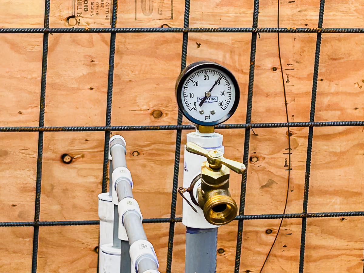
This test is performed before every gunite shoot. It is not a formality — it is the last opportunity to confirm the plumbing system is sound before it becomes part of the structure. The gauge reads at the equipment pad location where the plumbing manifold exits the shell.
Pre-Gunite Inspection — City of Rocklin
Before the gunite crew is scheduled, the project requires a pre-gunite inspection by the City of Rocklin building department. I scheduled the inspection for April 25, 2025, and coordinated directly with the building department so I could meet the inspector on site. They gave me a window — their schedule varies — and I waited on site that morning.
When the inspector arrived, I introduced myself. He was visibly surprised. He told me he usually doesn’t meet the builder on site. I explained that this project was out of the ordinary — the retaining walls added significant structural detail beyond a standard pool permit — and that I wanted to be available to answer any questions he had.
We walked into the site together. At the job jacket, I handed him the stamped letter from my structural engineer documenting his excavation inspection and soil determination. The inspector took the plans and went through the site meticulously — measuring the footings, checking the rebar, and referring back to the plans at each stage. He didn’t have any questions. When he finished, he said: “Looks good.” He signed off on the plumbing, electrical, and pre-gunite on the inspection card.
I called the gunite crew that afternoon. We had passed the pre-gunite inspection. They gave me a date, and the project was cleared for gunite.
Meeting the building inspector on site is not required. Neither was having the structural engineer inspect the excavation before the footing was formed. Both are standard practice on my projects. On an engineered hillside build with a five-foot structural retaining wall, these steps are not optional in my view — they are what responsible construction looks like.
Gunite Application: The Integrated Operation
On this Rocklin project, the gunite operation was two days. The pool shell, five-foot structural retaining wall, wing walls, and equipment wall were all shot as one continuous structural operation. This is not how all pool contractors approach retaining wall construction — but it is how an engineered system is correctly built.
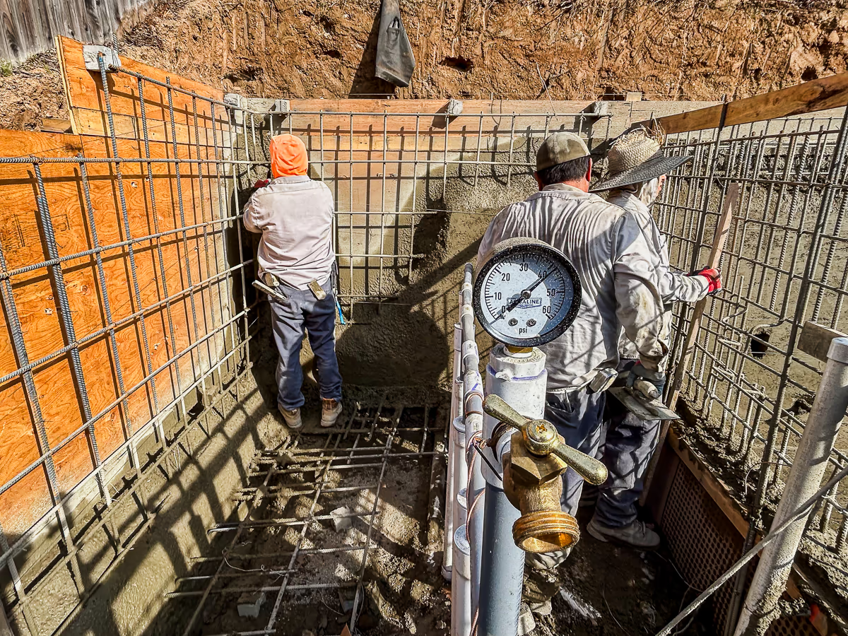
The gunite operation is sequential but continuous. The wall sections are worked first from lower elevations up, with the nozzleman establishing the base coat and the crew rodding the fresh surface to achieve the specified wall thickness. The pool floor and lower shell sections follow.
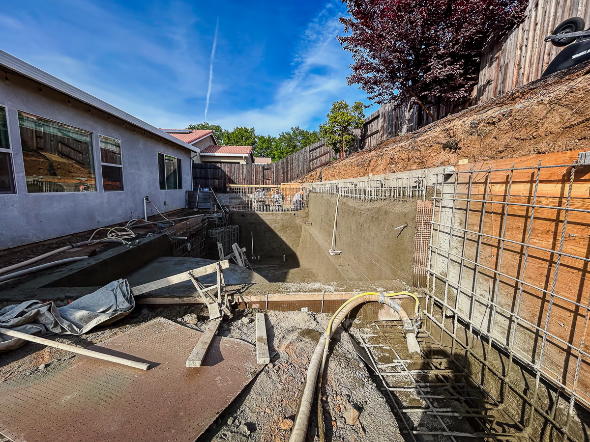
A 4-Foot Sheer Descent Waterfall: Design, Precision, and Four-Phase Execution
The raised equipment wall created an opportunity I did not want to miss. I designed a 4-foot sheer descent waterfall — not at the top of the wall, but positioned slightly below center where the proportion felt balanced against the full wall height. I wanted the falling water to feel inevitable, as though it belonged in the wall from the beginning.
Installing a 48-inch falls unit in a 10-inch wall requires precision at every phase. The centering is documented on the plans — 6 feet 7 and a half inches from each end wall to the edge of the opening, centered within the 13-foot-3-inch wall span. I drafted written plan sets for each crew involved — steel, plumbing, gunite, and tile — because each phase leaves something permanent that the next crew depends on.
During the plumbing phase, a 2-inch supply stub was positioned on the equipment side of the wall, aligned with the falls location. During the steel phase, the crew worked from my plan to build a reinforced cage around the 4-foot falls opening, leaving adjustment room on each side to align precisely with the final wall width. The centering had to be right before any gunite was applied. At gunite, we built a sturdy form at the falls opening and held it in position through the shoot. While the gunite was still green, we cut a slot in the wall from the back to accommodate the two 1.5-inch feed pipes serving the falls unit. Alignment was verified before the material set. The form stayed in place through the shell cure period, while the gunite was kept moist for approximately 14 days in accordance with the structural plans. The tile crew stripped the form, installed the falls unit, connected the supply plumbing, and completed the wall face.
The finished feature is the result of coordinated planning across four crews and four construction phases.
It looks simple. It was not.
The Craft of Gunite Application
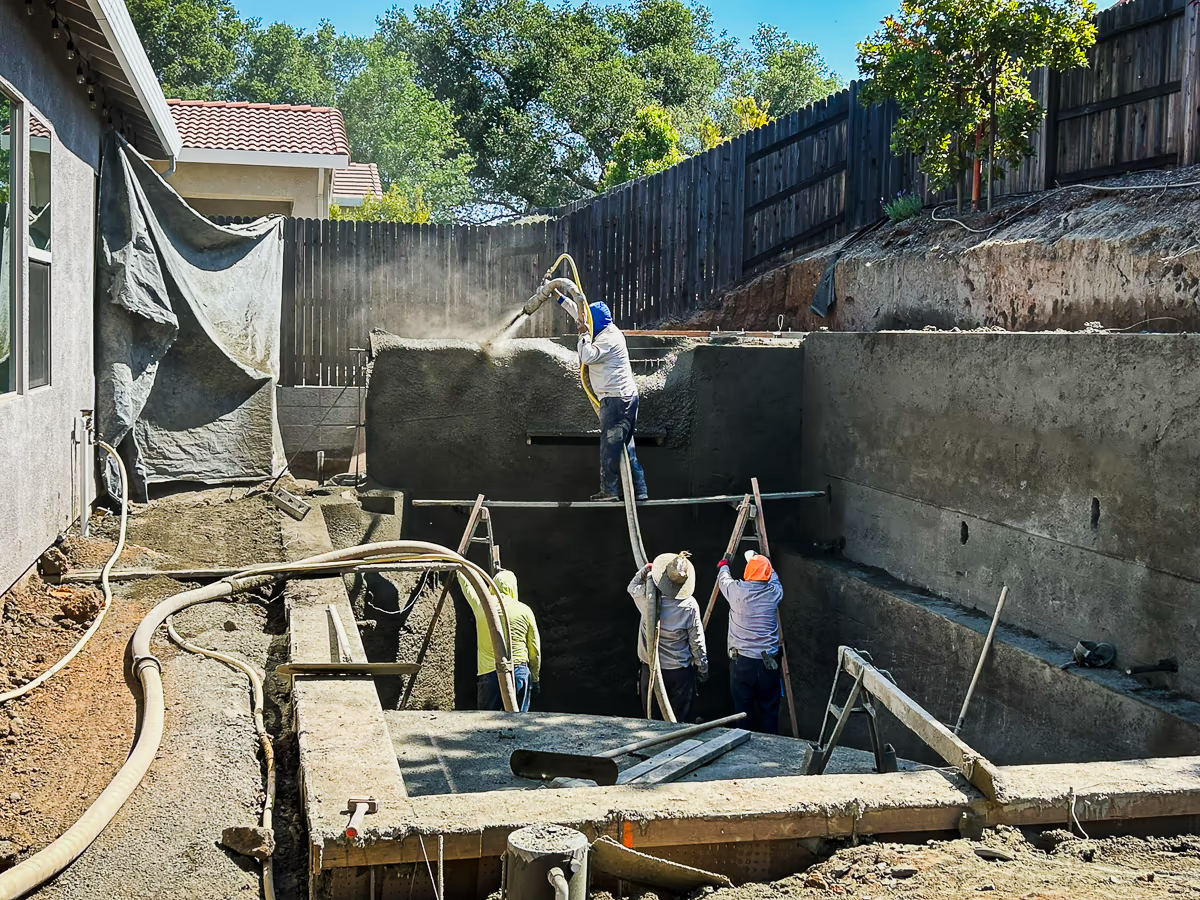
The nozzleman controls the angle, distance, overlap, and water content of every pass. A valve at the nozzle regulates how much water is introduced into the dry mix — water content directly affects the density and workability of the gunite as it is applied. These variables determine the density and bond strength of the finished shell. The structural plans specify a minimum compressive strength of 2,500 PSI at 28 days. On a retaining wall system, the nozzleman works from an elevated position to reach the upper sections, building the wall from the bottom up in lifts. The completed lower face is visible as the upper sections are worked.
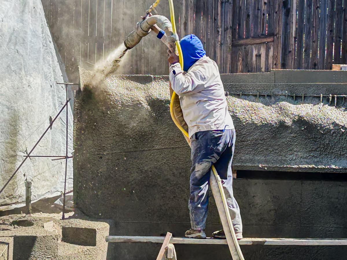
Gunite is pneumatically applied dry-mix concrete. The cement and aggregate are delivered dry through the hose and water is introduced at the nozzle. The high-velocity impact compacts the material against the rebar and form backing, building the wall to the thickness called for in the plans. Rebound material — the fraction that does not bond — falls away and is removed. What stays is the dense, well-compacted pool shell.
The Completed Gunite Shell
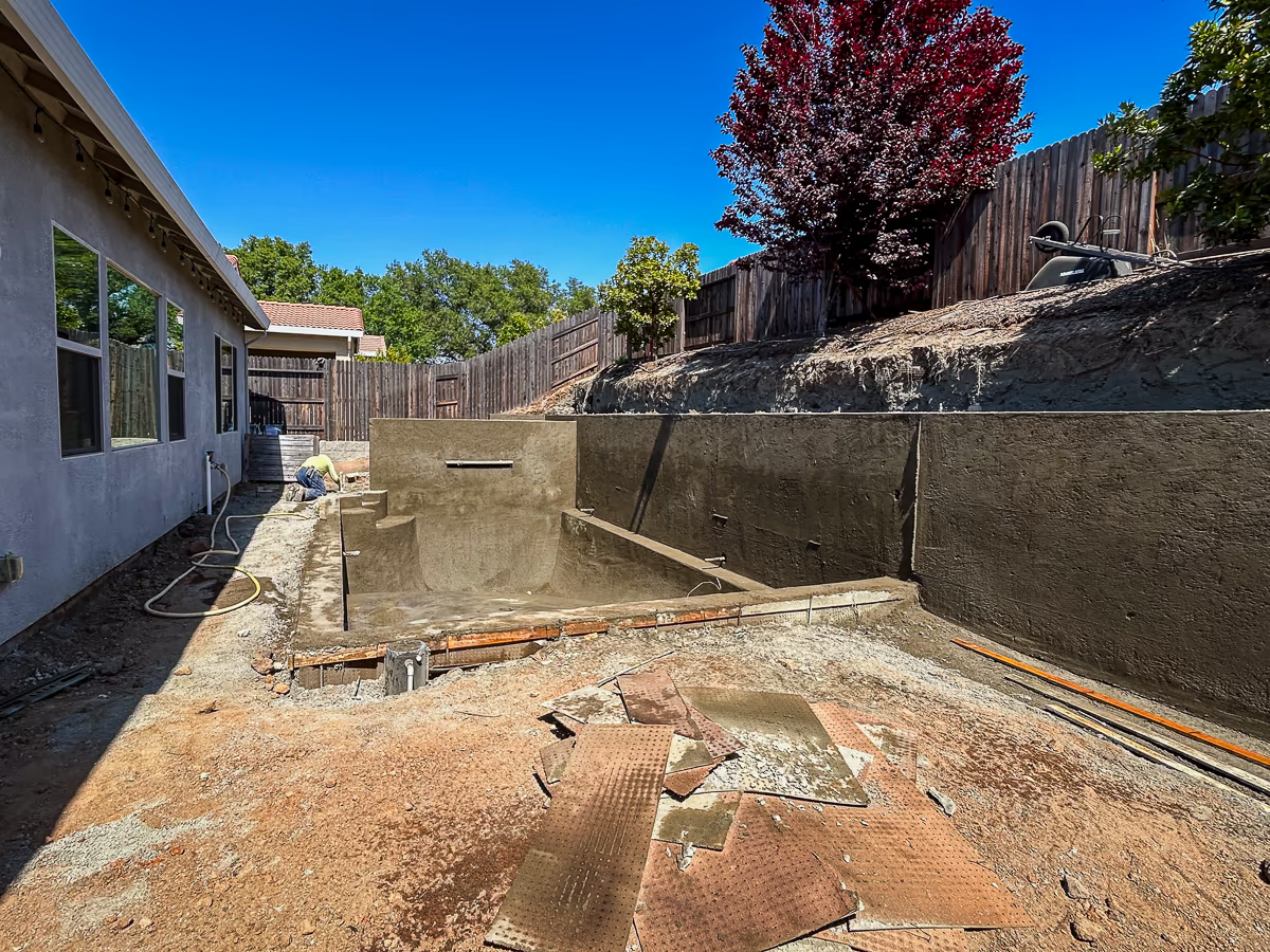
After two days, the pool shell and structural retaining wall system were complete. The pool shell, five-foot structural retaining wall, wing walls, and equipment wall are now one continuous monolithic structure. The hillside above documents the full nine feet of grade change the integrated wall system permanently manages.
Adjacent Retaining Wall Bond Break
Where the main structural retaining wall meets an adjacent retaining wall, the engineered plans specify a bond break and discontinuous reinforcement. This allows each element to move independently — preventing stress transfer between walls with different load conditions. The “wing” retaining walls are also structurally separated from the pool shell per the structural engineering requirements.
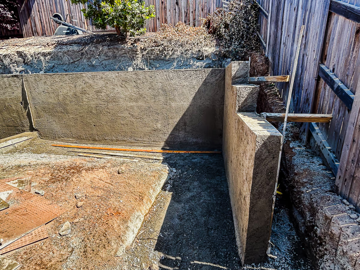
This detail is specified in the structural engineering drawings. It is not a field decision. On a hillside site where multiple retaining elements interact, the structural engineer defines exactly where continuity is required and where separation is required. The field crew executes to the plans.
The shell cure period follows gunite application. The pool is wetted and kept moist for approximately 14 days per the structural plans before tile and coping work begins. Post 4 covers the finished pool.
Does your yard have slope, limited access, or both?
The first step is a visual site consultation to determine what is actually buildable. If the project is a good fit, we move into a paid design consultation where everything is measured and engineered correctly.
Jim Chandler Pools Inc. has been building custom gunite pools in Rocklin, Placer County, and the greater Sacramento region since 1990. CSLB C-53 License #585004. Return to the Rocklin Small Yard Pool project overview.